
Volume 20 (March 2016) DOWNLOAD PDF
FEATURED ARTICLE:
Fan Filter Units: Design and Application Fundamentals
By David Surminski – Product Manager, GRD and Critical Environments
Fan Filter Units (FFU’s) are relatively simple devices, consisting of a filtered laminar flow diffuser with an integrated fan and motor. The integral fan is used to provide enough static pressure to overcome the pressure drop of the attached HEPA or ULPA filter instead of relying on the main Air Handling Unit (AHU); therefore, by using an FFU system, it is possible to greatly reduce the size of the AHU required.
An added benefit to using a decentralized system with multiple FFU’s means that potential downtime is mitigated. The loss of one FFU will have minimal effect on the overall system, whereas the loss of a central AHU would be very limiting. FFU’s were introduced into the market in the mid-1980’s for use in microelectronics manufacturing facilities. The FFU quickly became the design standard based on a few key advantages: decentralized air handling, high airflow capabilities and modularity resulting in the ability to add or remove individual units easily.

FFU installation in a Pharmacy
The ability to quickly create small mini-environments using multiple tightly packed FFU’s with individualized and specialized control is a popular option for many large cleanroom operations, where overall ISO classifications can be upgraded easily by adding FFU’s to increase room air change rates.
FFU’s are typically installed in two main configurations, the first of which draws air from a common plenum. One major advantage of a common plenum FFU system is that it inherently converts the ceiling plenum into a negative pressure space, thereby eliminating the risk of contaminants migrating from the ceiling plenum into the clean space below. The negative pressure is created as the FFU draws surrounding air from the common returns as well as fresh outside air from an AHU. In this configuration, the FFU should be selected with a constant flow motor program, which automatically adjusts motor torque and RPM in an energy efficient manner to overcome rising static pressure as the filter loads over time.
Alternatively, the FFU can be directly ducted from an AHU or terminal device. In this arrangement the FFU and upstream terminal are directly coupled, making it imperative that the two devices do not both attempt to actively control airflow rates. If a pressure independent Venturi Valve or Constant Volume Terminal are used to control the airflow rate, a constant torque motor program should be selected for the FFU to ensure that both systems do not fight against each other to maintain constant airflow into the space.
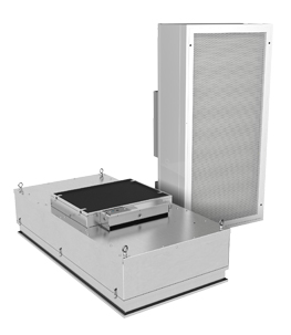
A Fan Filter Unit consists of a filtered laminar flow diffuser with an integrated fan and motor
If the ducted FFU is intended to maintain a constant airflow rate, then the constant flow motor program should be used in conjunction with an upstream manual balancing damper, rather than a pressure independent terminal. It is essential that the pressure at the ducted FFU inlet remain as close to neutral (0” w.g.) as possible.
When designing FFU systems, it is important to understand the features and options available to ensure reduced energy consumption and compliance with the required cleanliness standards. Common features and optional accessories are listed below:
- Common sizes of Fan Filter Units are 24”x48” and 24”x24”, designed to fit into standard heavy duty cleanroom ceiling grids.
- Plenum and frame construction is typically mill or painted aluminum, with optional stainless steel for demanding environments.
- Two types of filters are available: HEPA filters (99.99% efficiency at .3µm particle size) and ULPA filters (99.999% at .12 µm) for more stringent particle control.
- Filter frame styles include the standard bench-top replaceable filter, which requires the removal of the unit from the ceiling for filter replacement, and the room-side removable filter, with an integrated gel seal which allows filter changes to be completed below the installed unit.
- There are two available motor options: EC and PSC. The popularity of EC motors has been increasing over PSC motors. EC motors offer higher energy efficiency and ability to program for constant flow, and can be controlled with an external signal, such as through a Building Automation System (BAS) or BACnet system.
- An Aerosol Test System (ATS) is available. This system eliminates the need to gain access to any ductwork or plenum above the ceiling to complete the Aerosol Challenge and verify proper unit and filter operation. The ATS allows for aerosol to be injected into the FFU, upstream of the filter, through an integrated 3/8” NPT port which is accessible through the face of the unit.

Figure 1: Airflow in a common plenum FFU configuration
There are several options for controlling the Fan Filter Units depending on the level of control and monitoring/feedback desired.
Basic airflow control on PSC and EC motors is accomplished with a variable speed dial to set motor speed and the resultant airflow. This is typically set once at system startup and only adjusted if conditions or set points change in the future. Unlike PSC motors, which are not programmable, EC motors can be used with a constant flow program to maintain a desired airflow set point.
The EC motor speed controller can also accept a 2-10VDC signal through a BAS to control airflow remotely. Specialized EC motor configurations include deluxe versions with LCD displays for status monitoring and setting adjustment or the ability to control the unit through a BACnet system. Control and monitoring over BACnet allows for real-time filter static readings, thereby creating the opportunity for full optimization of energy consumption and filter replacement cost.
FFU’s have steadily increased in popularity due to their energy efficient design and reduced risk of downtime as a result of the decentralized air handling system. The modular design of FFU systems allows for quick and easy changes to ISO classifications of cleanrooms. FFU’s have many useful features and options which allow for complete customization of the system and a full range of feature-rich control options allowing for quick startup and commissioning, and full control and monitoring of the system during operation.
Product Feature
PRODUCT FEATURE:
Price’s UFAD Team Launches Moduflex System Solutions
Price’s Underfloor Air Distribution (UFAD) team has recently developed the new easy-to-apply ModuFlex system, providing zone-based solutions through a combination of UFAD and control components.
Continue to Article
TECH TIP:
Zone Level Moisture Load - Part Two
This Tech Tip provides an analysis of moisture loads for the application of a variety of products in different applications.
Continue to Article